Temperature Sensor - Multi-Zone Monitoring System
Objective: Create a temperature monitoring system with multiple LED indicators for different temperature ranges.
This project demonstrates analog sensor reading, mathematical calculations, and multi-conditional logic for environmental monitoring.
Required Components:
- Arduino Uno/Nano
- LM35 Temperature Sensor or TMP36
- 3 LEDs (Red, Yellow, Green)
- 3x 220Ω Resistors
- Breadboard
- Jumper wires
Temperature Zones:
- HIGH (≥50°C): Red LED - Danger zone
- NORMAL (30-49°C): Yellow LED - Comfortable zone
- LOW (<30°C): Green LED - Cool zone
#define TempPin A0
int TempValue;

void setup() {
  Serial.begin(9600);

  pinMode(2, OUTPUT);  // Red LED - HIGH TEMP
  pinMode(3, OUTPUT);  // Yellow LED - NORMAL TEMP
  pinMode(4, OUTPUT);  // Green LED - LOW TEMP
}

void loop() {
  TempValue = analogRead(TempPin);
  float TempCel = (TempValue / 1024.0) * 500;
  float TempFarh = (TempCel * 9) / 5 + 32;

  if (TempCel >= 50) {
    Serial.println("HIGH TEMPERATURE");
    digitalWrite(2, HIGH);
    digitalWrite(3, LOW);
    digitalWrite(4, LOW);
  }
  else if (TempCel >= 30 && TempCel < 50) {
    Serial.println("NORMAL TEMPERATURE");
    digitalWrite(2, LOW);
    digitalWrite(3, HIGH);
    digitalWrite(4, LOW);
  }
  else {
    Serial.println("LOW TEMPERATURE");
    digitalWrite(2, LOW);
    digitalWrite(3, LOW);
    digitalWrite(4, HIGH);
  }

  delay(500);
}
How it works:
- Temperature Conversion: Converts analog reading to Celsius using formula for LM35/TMP36.
- Multi-Zone Logic: Uses if-else statements to categorize temperature ranges.
- LED Indicators: Only one LED lights up at a time based on current temperature.
- Serial Output: Displays temperature status on serial monitor.
- Real-time Monitoring: Continuously monitors and updates every 500ms.
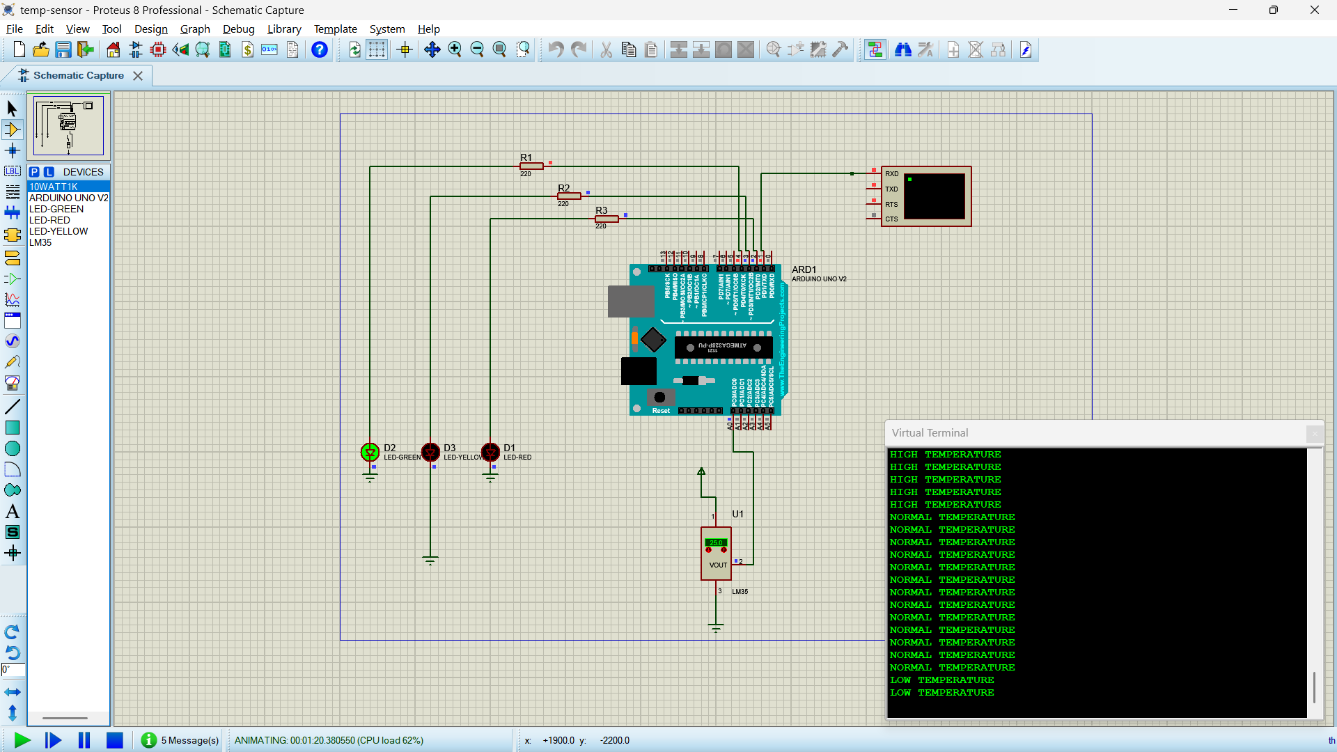
Circuit Connection:
- Temperature Sensor: VCC to 5V, GND to GND, Signal to A0
- Red LED: Pin 2 → 220Ω resistor → LED → GND
- Yellow LED: Pin 3 → 220Ω resistor → LED → GND
- Green LED: Pin 4 → 220Ω resistor → LED → GND