Light Dependent Resistor (LDR) - Automatic Light Control
Objective: Create an automatic light control system using LDR sensor that turns LED on/off based on ambient light levels.
This project demonstrates analog input reading and conditional logic for creating responsive IoT systems.
Required Components:
- Arduino Uno/Nano
- LDR (Light Dependent Resistor)
- LED
- 220Ω Resistor (for LED)
- 10kΩ Resistor (pull-down for LDR)
- Breadboard
- Jumper wires
// the setup routine runs once when you press reset:
void setup() {
  // initialize serial communication at 9600 bits per second:
  Serial.begin(9600);
  pinMode(10, OUTPUT);
}

// the loop routine runs over and over again forever:
void loop() {
  // read the input on analog pin 0:
  int sensorValue = analogRead(A0); // A0 PIN IS SET HERE

  // print out the value you read:
  Serial.println(sensorValue);

  if(sensorValue < 15)
  {
    digitalWrite(10, LOW);
  }
  else
  {
    digitalWrite(10, HIGH);
  }

  delay(100); // delay in between reads for stability
}
How it works:
- analogRead(A0): Reads analog value from LDR connected to pin A0 (0-1023).
- Serial.println(): Prints sensor values to serial monitor for debugging.
- Threshold Check: If light level is below 15, LED turns off (dark environment).
- Auto Control: LED automatically turns on when it gets bright enough.
- delay(100): Small delay for stable readings and to avoid flickering.
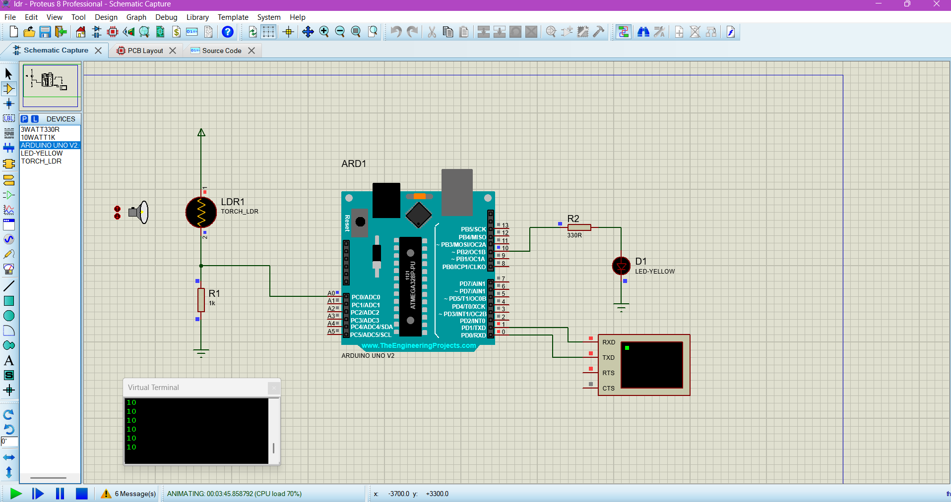
Circuit Connection:
- LDR: One end to 5V, other end to A0 and 10kΩ resistor to GND
- LED: Anode to pin 10 through 220Ω resistor, cathode to GND